

News
UV Picosecond Laser Cutting: The Revolutionary Choice for Precision Graphite Sheet Processing
In today’s rapidly evolving tech landscape—driven by 5G communications, semiconductor packaging, advanced EV power systems, and high-performance consumer electronics—thermal management dictates device reliability. High-thermal-conductivity graphite sheets (including synthetic graphite films, flexible graphite, and graphene composite films) have become the gold standard for heat dissipation due to their exceptional thermal conductivity, lightweight nature, and flexibility.
However, these advanced materials present significant manufacturing hurdles. High-purity graphite is inherently brittle, anisotropic, prone to particulate flaking, and exceptionally fast at conducting heat. Traditional die-cutting, mechanical routing, and legacy long-pulse infrared lasers frequently cause delamination, thermal damage, and edge defects.
Ultraviolet (UV) picosecond laser cutting technology solves these challenges. Below is an in-depth look at the unique processing demands of ultra-thin graphite and why UV picosecond lasers have emerged as the definitive tool for high-precision manufacturing.
1. The Core Challenges of Machining Ultra-Thin Graphite Sheets
To understand the breakthrough of UV picosecond processing, it is essential to first address the physical limitations of graphite sheets:
Anisotropy and Delamination Risk: High-thermal-conductivity graphite features a layered crystalline structure. While in-plane thermal transfer is high, inter-layer bonding strength is relatively low. Mechanical shear forces often cause edge delamination, fraying, or tearing.
Rapid Thermal Diffusion: With an in-plane thermal conductivity reaching 1,500–1,800 W/(m·K)—several times higher than copper—graphite conducts heat almost instantly. Conventional thermal cutting (such as long-pulse nanosecond or infrared lasers) rapidly spreads heat outward, creating a wide Heat-Affected Zone (HAZ) that leads to edge scorch, carbonization, and structural degradation.
Micro-Cracking and Dust Contamination: Graphite’s brittleness makes it susceptible to micro-cracks under mechanical contact. The resulting graphite dust can contaminate sensitive cleanroom environments or cause electrical shorts on nearby electronic components.
Ultra-Thin and Complex Geometry Requirements: As device internal architecture becomes increasingly compact, graphite film thickness has scaled down to tens of microns, often requiring complex micro-features. Traditional mechanical dies suffer from rapid blade wear, high tooling costs, and an inability to maintain tight tolerances (±5 μm).
2. The Physics Behind the Breakthrough: 355nm UV + Picosecond Pulse Width
The UV picosecond laser solves these material challenges by combining two distinct physical capabilities:
355nm Short Wavelength (Photochemical Cold Processing):
Unlike infrared (1064nm) or green (532nm) lasers that rely heavily on thermal melting, 355nm UV photons carry high single-photon energy. This energy directly breaks the carbon-carbon (C-C) molecular bonds within the graphite matrix through photochemical photoablation, vaporizing the material without generating excess heat.
Picosecond Pulse Duration (Photothermal Confinement):
A picosecond is one-trillionth of a second (10-12s). Delivering laser energy in ultra-short bursts allows energy to accumulate faster than heat can transfer between electrons and the crystal lattice. Material is ablated and ejected before heat can diffuse into the surrounding substrate.
The combination of photochemical bond-breaking and ultrafast pulse confinement yields a true cold-machining process ideal for heat-sensitive materials.
3. UV Picosecond Laser Cutting vs. Legacy Methods
Comparing UV picosecond lasers with conventional processing techniques highlights the operational differences across key metrics:
Processing Mechanism: Mechanical die-cutting relies on physical shear stress; infrared/green nanosecond lasers use thermal melting and evaporation; UV picosecond lasers utilize ultrafast photochemical ablation and cold gasification.
Heat-Affected Zone (HAZ): Mechanical methods produce no heat (but introduce structural stress); legacy lasers create a large HAZ with edge scorching; UV picosecond cutting maintains a near-zero, micron-scale HAZ.
Edge Quality: Die-cutting causes burrs, delamination, and edge collapse; legacy lasers leave oxidation, melt beads, and heavy carbon dust; UV picosecond processing yields smooth, clean, and burr-free edges.
Dimensional Accuracy: Mechanical dies typically deliver around ±50 μm; legacy lasers achieve roughly ±20 μm; UV picosecond laser systems achieve strict tolerances within ±5 μm.
Tooling and Wear: Physical blades suffer high wear and require costly replacement; laser processing is entirely non-contact, eliminating mechanical tool degradation.
Prototyping & Flexibility: Mechanical methods require days for new die fabrication; UV picosecond systems run directly off CAD files for instant design changes and zero retooling costs.
4. Primary Benefits for Industrial Production
Integrating UV picosecond laser cutting into high-precision manufacturing lines offers measurable performance improvements:
Clean Edges Without Delamination: The ultrafast pulse duration eliminates mechanical tearing, restricting edge chipping to under 10 μm and preserving the structural integrity of the layered graphite.
Particle and Dust Mitigation: Because the graphite carbon is directly vaporized and swept away by integrated extraction systems, edge carbonization and loose particles are minimized—ensuring compatibility with sensitive electronics assembly.
Multi-Layer Composite Processing: Modern thermal designs frequently combine graphite with PET, double-sided adhesives, Polyimide (PI) films, or copper foils. Thanks to the high absorption rates of UV light across both organic and inorganic materials, UV picosecond lasers cut multi-layer stacked composites cleanly in a single pass without adhesive bleeding or edge charring.
Faster R&D and Lower Tooling Overhead: Digital CAD-driven processing eliminates the need for expensive physical dies, lowering prototyping costs and enabling rapid engineering change orders (ECOs).
5. Key Industry Applications
UV picosecond graphite laser cutting systems are deployed across several demanding manufacturing sectors:
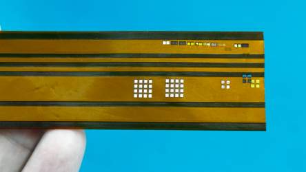
Smartphones and Foldables: Precision cutting of ultra-thin, high-conduction synthetic graphite and graphene heat-dissipation films with intricate internal cutouts.
Semiconductor & Advanced Packaging: Manufacturing precision graphite thermal interface materials (TIMs) and heat-spreader pads for high-performance processors (CPU/GPU/AI accelerators).
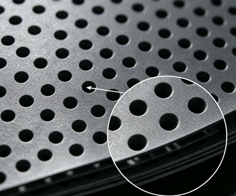
EVs and Energy Storage: High-precision profiling of graphite bipolar plates and ultrathin graphene-coated electrode sheets for fuel cells and advanced battery architectures.
Medical & Aerospace Electronics: Producing ultra-clean, micro-scale graphite thermal components where zero particulate contamination is mandatory.


-
What are the precautions for operating a laser marking machine?
1. It is strictly prohibited to start the laser power supply and Q-switching power supply when there is no water or the water circulation is abnormal.
2. The Q power supply is not allowed to operate without load (i.e., the output terminal of the Q power supply should be left floating).
3. In case of any abnormal phenomenon, first turn off the galvanometer switch and the key switch, and then conduct a check.
4. It is not allowed to start other components before the krypton lamp is lit to prevent high voltage from entering and damaging the components.
5. Pay attention to leaving the output terminal (anode) of the laser power supply suspended to prevent sparking and breakdown with other electrical appliances.
6. Keep the internal circulating water clean. Regularly clean the water tank and replace it with clean deionized water or pure water.
-
What should we do when laser intensity decreases and the marking is not clear enough?
1. Turn off the machine and check if the laser resonant cavity has changed; Fine-tune the resonant cavity lens. Make the output light spot the best;
2. The acousto-optic crystal is offset or the output energy of the acousto-optic power supply is too low;
Adjust the position of the audio-visual crystal or increase the working current of the audio-visual power supply;
3. The laser entering the galvanometer deviates from the center: Adjust the laser;
4. If the current is adjusted to around 20A but the light sensitivity is still insufficient: the krypton lamp is aging. Replace it with a new one.
-
How to maintain a UV laser cutting machine?
1. It is required to carry out regular cleaning every day, remove debris from the countertop, limiters and guide rails, and spray lubricating oil on the guide rails
2. The waste materials in the collection box should be cleared regularly to prevent excessive waste from blocking the exhaust port.
3. Clean the chiller once every 15 days, drain all the internal water, and then fill it with fresh pure water.
4. The reflector and focusing lens should be wiped with a special cleaning solution every 6 to 8 hours.
When wiping, use a cotton swab or cotton swab dipped in the cleaning solution to wipe from the center to the edge of the focusing lens in a counterclockwise direction.
At the same time, be careful not to scratch the lens.
5. The indoor environment can affect the lifespan of the machine, especially in damp and dusty conditions.
A damp environment is prone to causing rust on the reflective lenses and also easily leading to short circuits, discharge and sparking of the velvet laser.
-
What accidents might be caused by the laser emission when using a laser cutting machine?
(1) A fire was caused by the laser coming into contact with flammable materials.
Everyone knows that the power of laser generators is very high, especially when it comes to high-power laser cutting machines, the temperature of the emitted laser is extremely high. The possibility of a fire being caused when a laser beam comes into contact with flammable objects is very high.
(2) Harmful gases may be produced when the machine is in operation.
For instance, when cutting with oxygen, it undergoes a chemical reaction with the cutting material, generating unknown chemical substances or fine particles and other impurities. After being absorbed by the human body, it may cause allergic reactions or discomfort in the lungs and other respiratory tracts. Protective measures should be taken when conducting work.
(3) Direct laser exposure to the human body can be harmful.
The damage caused by lasers to the human body mainly includes damage to the eyes and skin. Among the harms caused by lasers, the damage to the eyes is the most severe. Moreover, damage to the eyes is permanent. So when doing homework, you must pay attention to protecting your eyes.
-
What is the focused spot diameter of nanosecond, picosecond and femtosecond laser?
Nanosecond: The light spot is 0.5-1mm.
Picosecond: The focused spot is around 0.02mm.
Femtosecond: Under the action of a laser beam with a high repetition rate of 100-200KHz and a very short pulse width of 10ps,
the focused spot diameter is as small as 0.003mm.
-
What are the main applications of UV laser cutting machine?
The UV laser cutting machine can be used for cutting and depaneling PCB.
It can precisely cut and shape various types of PCB circuit boards with V-CUT and stamp holes, and open Windows and covers.
It can also be used for separating packaged circuit boards and ordinary smooth boards.
It is suitable for cutting various types of PCB substrates, such as ceramic substrates, rigid-flex boards, FR4, PCBs, FPCs, fingerprint recognition modules, cover films, composite materials, copper substrates, aluminum substrates, etc.
-
Precautions for laser cutting machines to process various metal materials?
Copper and brass:
Both materials have high reflectivity and excellent thermal conductivity.
Brass with a thickness of less than 1mm can be processed by nitrogen laser cutting.
Copper with a thickness of less than 2mm can be cut. The gas used for laser cutting processing must be oxygen.
Copper and brass can only be cut when a "reflective absorption" device is installed on the system. Otherwise, reflection will damage the optical components.
Synthetic materials:
Processable synthetic materials include: thermoplastics, thermosetting materials and artificial rubber.
Aluminum:
Despite its high reflectivity and thermal conductivity, aluminum materials with a thickness of less than 6mm can be cut, depending on the type of alloy and the capacity of the laser.
When cutting with oxygen, the cutting surface is rough and hard.
When nitrogen is used, the cutting surface is smooth.
Pure aluminum is extremely difficult to cut due to its high purity.
Only when a "reflection and absorption" device is installed on the fiber laser cutting machine system can aluminum materials be cut.
Otherwise, reflection will damage the optical components
-
What should be paid attention to when laser cutting stainless steel?
Laser cutting processing of stainless steel requires the use of oxygen, under the condition that edge oxidation is not a concern.
If nitrogen is used to achieve an edge free of oxidation and burrs, no further processing is required.
Coating an oil film on the surface of the sheet will achieve a better perforation effect without reducing the processing quality.